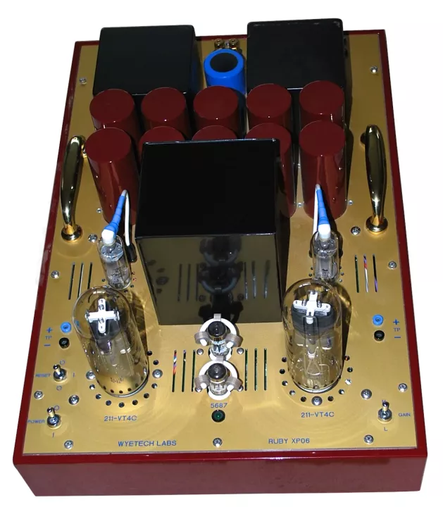
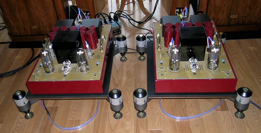
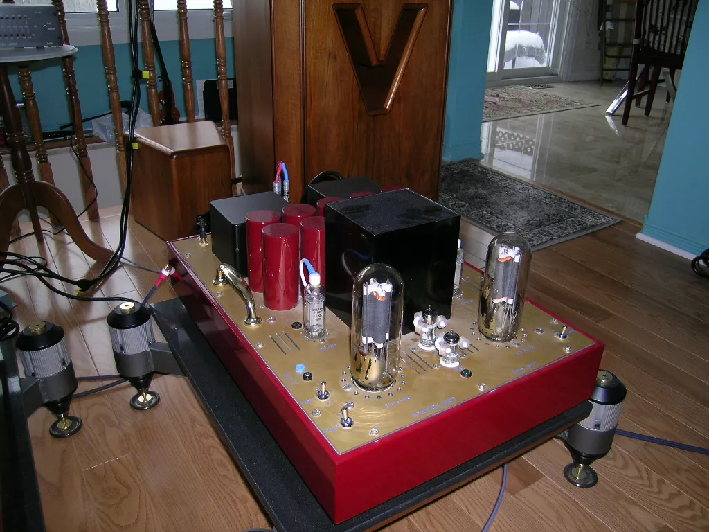
Reference single ended triode (SET) monoblock amplifier
The Ruby series of products is a culmination of my experience and knowledge gathered over the last 20 years resulting from my insatiable desire to reach as close to perfection as possible.
This unit is unique since only one pair was built using the Alum Rock 25 pound custom potted output transformers with a single secondary 8 Ohm output winding for maximum frequency response. Bob Potter is a magnetics engineer who formally designed transformers for NASA in California. He is an obsessive perfectionist who has built his own SET amplifier in order to demonstrate his design talent. [ cost: $85,000 ]
The frequency response has been designed to be linear within +/- 0.5 dB from 20 to 24,000 Hz and weighs in at 25 pounds each.
Gallery

Circuit Description
Voltage Stage
This stage operates in pure class "A1" single ended plate loaded and automatic self-biasing circuitry.
Gain Switch
High Gain = 28.5 db
Low Gain = 23.0 db
Driver Stage
This stage also operates in pure class "A1" single ended plate loaded with automatic self-biasing circuitry. This stage operates with high bias current and high voltages needed to drive the output tubes and do so without driving the grids positive to insure no grid current drive is required. The AC signal is coupled to the 211 grids via 2 independent metalized high voltage, high capacitance Teflon signal capacitors with self healing ability and 1300 Volt DC rating.
211 Output Stage
Both 211 output tubes also operate in pure class "A1" single ended self-biased isolated circuitry and transformer coupled for 8 Ohm speaker output. Built with special custom output transformers from Alum Rock Technology.
Other Features
Dual female jacks to monitor the bias of each tube. Use a Volt meter on 100 Volt range
A front mounted gain switch is used to select high and low gain as required.
The 211 filaments, which also act as the cathode for each triode, require isolated pure 10 volt DC power supplies. Each of the two supplies have a separate AC secondary winding connected to a full wave 25 Amp bridge rectifier followed by a 120,000uf filter capacitor to reduce the ripple below audibility.
Two 211's are used in parallel by tying the top plates of each to drive the primary of the output transformer. Each tube is independently self - biased.
Ground loop hum is not a problem - there is no ground lift switch on any Wyetech Labs amplifiers. We employ a special network that does not remove ground safety from the chassis. As a consequence Wyetech monoblock amps don't suffer from ground loop hum pickup!
We are using only pure capacitors and inductors to filter the dual high voltage power supplies. Because of this it took a large chassis with each monoblock measuring 16.5" x 24" to hold and accommodate the parts needed to implement this type of pure power supply.
The output transformer reacts to this configuration in such a way that it thinks it has only one tube with two times the power rating of one 211 driving it. Because of this the impedance ratio [ 5000 ohms ] of the output transformer is halve of that required with only one tube.
A single 8 ohm output winding in the transformer was implemented to obtain the exact winding turns without any taps to maintain the most linear frequency output possible with one continuous copper winding.
A comparator circuit monitors each output tube. If the bias goes out of the acceptable range it turns on it's corresponding red LED fault light. In this case it's normally time to change this tube.
Power Supplies
Three Toroid power transformers are used in each monoblock with input AC power operation for 115V/230V 50-60 Hz selected via an internal toggle switch.
Separate DC power supply filtering provide total isolation between the INPUT and OUTPUT stages. This consist of a quadruple4 (pi) filter for both the 500 Volt front end supply and the 1.2 Kilovolt output stage power supply.
Twin bridge rectifiers rated at 12,000 Volts DC and 0.55 Amps provide the needed voltage & current, that in turn feed the 6D22S [6Kv rating] rectifier tubes that enable the voltage to slowly ramp up due to the 30 second delayed warm up.
The use of pure LC filter networks with 10 very large polypropylene in oil capacitors, 1 large polypropylene capacitors and six large chokes provide an unparalleled ripple reduction and purity of design unequalled in tube SET amplifiers.
Rectified, filtered and regulated 12 Volt DC provides the power for the input tube filaments of the 1st and 2nd stage. This provides a very low noise floor that allows a blacker background between notes.
Mechanical Construction
Extremely rugged all welded steel chassis with 4 mm aluminum top and bottom plates provide a solid firm structure by design. Think of a picture frame doubled up and back to back with the flat top & bottom pieces flush mounted and bolted with 28 stainless steel dress machine screws. This reduces any possibility of vibration induced aberrations affecting the operation of the amplifier tubes.
Highly polished 6 inch solid brass handles allow for easy handling and accentuate the chassis styling.
Very high quality paint with primer coat and baked on finish to further enhance the beauty of the very symmetrical arrangement of parts.
A deep red & gold colour mix accentuates the cast aluminum satin black finish of the output & power transformers
Gold plated machined brass holder with 3M rubber feet inserts accentuates the styling and allows proper air flow for the vents under the chassis
Teflon Gold plated machined brass tube pin connectors for 5687and 12B4A sockets for an absolute secure connection and lifetime reliability
Ceramic / Aluminum large 4 pin sockets for the 211 tubes and ceramic sockets for the high voltage 6D22S rectifier tubes.
Circuit Boards
The components are mounted on three Printed Circuit boards [PCB] which is made from FR4 glass epoxy with double sided copper traces and plated through holes. Both sides have a protective green solder mask. A silkscreen is printed in white showing the component layout and parts value. This PCB was designed manually with CAD program in house. It has enlarged power and signal line traces to attain the best analog integrity that automatic CAD routing circuit programs cannot attain.
The final assembly of parts to the PCB is done by hand soldering of all components, which is superior to automated flow-soldering techniques, by allowing more solder on each and every joint.
Wiring to the PCB is attached via screw down crimp terminals to allow for ease of repair or removal.
Auto Power Sequencing
A built in time-delay of about 30 seconds in the 6D22S rectifier tubes allows for a slow smooth increase in final DC voltages to eliminate any noise on power up.
This also provides extended tube life and proper power sequencing for stabilized circuitry on power up.
Power Switches
Two toggle switches are employed for powering up the unit. The master switch enables the power and the momentary RESET switch engages the power relay to enable the automatic sequencing of operation until the green [ready] LED comes on after the initial time delay. In case of AC electrical power failure during a storm or other event the unit stays powered down until the RESET switch is again enabled. To use the RESET power switch it is important to hold down the toggle for 2 seconds until you hear a relay turning on before disengaging the switch.
We employ a delayed DC power sequencing that maximizes tube life by preventing cathode emission deterioration.
Low frequency response has been greatly enhanced by using very large signal capacitors and wide bandwidth custom output transformers. These combined attributes reduce overall distortion at higher power levels and give an overall impression of a much more powerful amplifier than what the specifications would suggest.
Power Down Sequence
The master switch is used to power down the unit. On activation of this switch a fixed time delay occurs that drops power to the speaker mute relay thereby shorting the speaker output before dropping the power sequence relay thus ensuring silence on powering down.
Burn-In Procedure For New Output Tubes
The tubes supplied with the unit will have already been tested in a system for about 10 hours. Things will improve over time and should reach nominal performance level after about 200 hours. On power up it will take about 15 minutes to reach optimum performance.
The bias voltage can be tested using a voltmeter. The reading should be around 70 Volts DC. [ usable range 65 V to 75 Volts ]
If either leg of the 211 tubes go out of that range the red LED L & R fault light will come on suggesting that this tubes should be replaced. The left tube fault light is designated FL and the right tube is designated FR.
Specifications
Tube Complement (per monoblock)
- 1 - 5687WB JAN NOS Philips USA - voltage stage - T1
- 1 - 12B4A JAN NOS GE USA - driver stage - T2
- 2 - Svetlana 6D22S high current high voltage rectifier - slow 30 second turn on.
- 2 - GE NOS VT4-C 211
Frequency Response
20 Hz to 24 KHz +/- 0.5 db
Input Impedance
28 K Ohms
Gain
- 28.5 dB > 0.65 VRMS HIGH
- 23.0 dB > 1.2 VRMS LOW
Absolute Phase
non-inverting
Power Output
36 Watts RMS
Dynamic Headroom
music peaks up to 72 Watts
Universal Voltage Select ( internal )
115/230 Volts 50/60 Hz
Power Consumption
385 Watts - 510 VA (each monoblock)
Weight
Net: 2 x 80 lbs. (31 kg)
Shipping: 2 x 90 lbs. (41 kg)
Dimensions
16.5" W x 24" L x 10" H
41.91 cm W x 60.96 cm L x 25.4 cm H
Warranty
Note that due to the passing of Roger Hebert, we are no longer able to offer warranty coverage going forward. The sale price has been adjusted accordingly. Sales made previous to January 2022 will have the waranty coverage period honoured.
Warranty coverage for sales prior to January 2022:
- Tubes: 1 year
- Components: 5 Years parts and labour
