audio power level meter
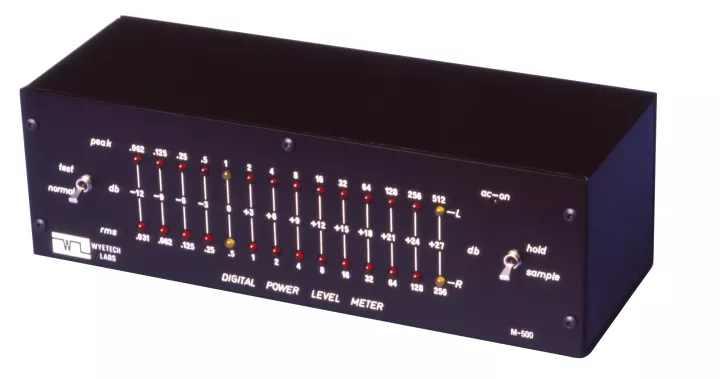
The model M-500 is a highly accurate audio power level meter employing analog to digital circuitry to indicate instantaneous peak power levels. Operating in a true peak sample and hold fashion, it converts peak voltage applied to the speakers to equivalent power levels for an 8 OHM load. For reference or testing purposes an additional calibrated scale shows the RMS power level when using a sine wave test signal.
A total of 14 LED (light-emmiting-diodes) indicators per channel give it a dynamic range of 42 dB. This allows it to functionally perform at any output power level without the need for switching ranges when changing volume levels. This avoids overload damage which can occur when a meter is set to a low power range and high power is accidentally applied.
The ultimate in simplicity of operation, it has the technical sophistication making its performance and reliability unsurpassed at any price.
Circuit Description
Peak Detector Network
Peak detection should not be confused with the commonly used averaging or VU type metering. These circuits usually employ "RC" type filtering of the audio signal. This increases the decay time while drastically reducing the input response sensitivity. The resulting ballistics not only render it incapable of measuring peaks, but give it a pulse response that would hardly extend much beyond 100 Hertz!
Our peak detector circuit has no capacitive delay in the signal path. This ensures ultra-fast peak response (rise-time) with bandwidth extending from DC to beyond one-quarter megahertz!
Decay and Hold Network
A unique circuit design extends the light duration (decay time) so that even the shortest of peaks are visible.
Test Function
A special test mode feature, employing a ramp generator circuit, gives visual assurance of the correct performance ofall functions and indicators.
With switches set to Sample + Test all LED's turn on in sequence from left to right. After remaining on for a short period, they will then turn off in opposite sequence. This ensures proper functioning of the peak detector and decay circuits.
With switches set to Hold + Test all LED's will remain on verifying proper Gperation ofall holding circuits.
Other Features
- Miniature soft-glow power on LED indicator.
- Individually factory-calibrated.
- Integrated circuit sockets for all IC's.
- Quality industrial grade switches.
- G10 glass epoxy printed circuit board.
- Low power consumption -6 Watts Idle -24 Watts Max.
- Inter-connecting cable included.
Specifications
- 14 LED indicators per channel.
- Dynamic range -42db.
- Calibrated scales: (Ref: Odb = 1 watt Peak@ 8 OHMS)
- Decibels from -12 db to +27 db in 3 db steps
- Peak Watts from 1/16 Watt to 512 Watts
- RMS Watts from 1/32 Watt to 256 Watts (Sinusoidal ref.).
- Modes of operation:
- Sample -continuous peak sampling with optimum decay time
- Hold - continuous peak sampling while holding indefinitely
- Test - Internal ramp generator checks functions and LEDs
- Rise time: 4 µs.
- Decay time: 4 ms.
- Channel balance -0.25 db (Odb and above).
- Input impedance -18K OHMS resistive (negligible loading).
- Power bandwidth -DC; 0.25 MHZ.
- Semi-conductor complement: 69 + 8 IC's + 1 regulator IC.
- Cabinet -Black aluminum 3.75" (9.5 cm) H x 12" (30.5 cm) W x 4" (10.2 cm) D.
- Power required -120 volts, 60 CY, 24 Watts Max.
Warranty
3 years, parts and labour
